section-00087c8
section-e9a4d85
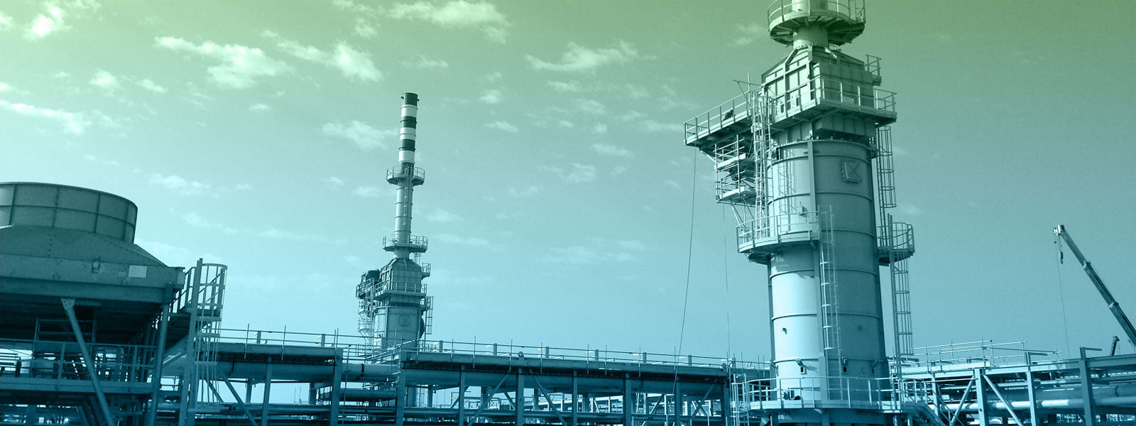
Direct Fired Heaters
Integraheat has decades of experience and development of fired heaters particularly designed to API 560 & ISO13705. With a proven track record of successful engineering, design and supply of our direct fired heaters, we have maintained client relations and confidence in our capabilities as an upcoming competitor against the big players in the fired heater industry. Our company offers a dynamic approach when considering the design aspect of fired heaters to control cost and feasibility of construction when considering assembly and installation. We have the experience to offer modularised fired heaters for easy construction on a turnkey project where we delivery the project from engineering to operation.
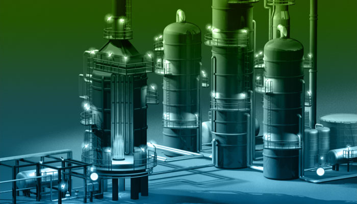
Direct Fired Heaters are used for multiple heating requirements though mainly associated with heating crude oil. Direct Fired Heaters come in a variety of designs depending on the application requirement. Integraheat have 3 main design types for Direct Fired heaters – Cylindrical, Box and Cabin Types. The most common type is the Cylindrical heater with vertical coils. Cylindrical heaters with helical coils are also provided for smaller heater duties.
Direct Fired Heater Design Concepts
- Vertical Cylindrical heaters
- Horizontal tube heaters (“cabin heaters”)
- Vertical tube “Box” Heaters
All these heaters have common features, particularly:
A radiant section (or “firebox” ) lined with heat-retaining refractory, where the “tubes” making up the heating coil are exposed to direct radiation from the burner flames.
Burners, firing fuel gas, fuel oil or a combination of fuels, mixed with a controlled quantity of combustion air. The combustion air may be induced by the natural draft effect of a heater stack, or supplied via a centrifugal fan, at ambient temperature or pre-heated.
Normally, a heat recovery section is provided where heat is extracted from the products of combustion leaving the radiant section by one or more convection section coils. In a convection section, heat transfer is partly by radiation but largely by convection, often enhanced by finned steel (“extended surface”) welded to the outside of the coil tubes.
Direct-fired heaters are also used in chemical and petrochemical plants where large amounts of heat have to be applied to a process or a feedstock raised to high temperatures. In these, generally less arduous applications, the client often accepts some relaxation of the standards laid down for refinery-type heaters. A typical example is the “hot oil” heater used for maintaining the temperature of a circulating heat transfer oil used to apply heat through heat exchangers to various processes in a plant.
The vertical cylindrical heater has been used for decades and offers a minimum demand on capital investment and available site space. Consequently it is the most widely used type of direct-fired heater and is the first choice for most refinery and general heating applications.
Our furnace employs the shell as the structure and plate thickness is consequently robust, avoiding the possibility of warping and damage to the refractory whilst minimising noise transmission. The entire construction presents a clean and easily maintained exterior appearance.
The use of vertical tube furnaces on crude and reduced crude vaporisation service presents special problems and such units are only offered once we have satisfied ourselves that flow stability can be maintained over the full turn-down range of the unit. Unstable phase separation in long length downflow tubes has occurred when designers have failed to pay proper attention to the problems of flow regime and in tube velocity, leading to rapid coking and tube failure.
The Horizontal Tube Heater
Also known as the Cabin Heater, this is the most rugged and most flexible type of furnace design. This type of heater need not cost much more than a vertical heater of the same size, particularly for larger units and when removable plug “clean-out“ fittings are specified for the coil. Furnaces of this type are the first choice for difficult vaporising services where the type of flow regime inside the coils is a problem.
Some designs are fired towards a center partition wall of refractory firebrick, giving maximum protection against upsets in the fuel supply or burner malfunction.
The location of flue gas removal ducting and convection section intermediate tube-sheets is properly arranged to ensure uniform heat transfer over the full length of the furnace.
Fine control over the temperature level of the different coil passes on furnaces serving large crude, or reduced crude units, is achieved by dividing the furnace into cells. These cells will each have the minimum number of coil passes exposed to a row of burners so that the firing rates can be trimmed as required.
Partition walls of refractory firebrick are sometimes used to “zone” furnaces to give control over heat flux in different areas of the coil.
The Vertical Tube Box Heater
Vertical tube box heaters combine low cost and minimal space requirements of vertical heaters with the control over the local firing rates inherent in the horizontal tube heater. These heaters are particularly suited to the larger installations where a number of units are operated simultaneously and can economically be combined in a single shell.
Conventional burners firing either vertically or horizontally can be offered, or specialised burners for "radiant wall" firing.
Of special interest is are design of 'Catalytic Reforming' type units. Coil designs for high intrinsic flexibility supported by constant load spring hangers external to the furnace permit the location of terminal nozzles adjacent to the reactor nozzles. This design can absorb essentially all the thermal movements of customers reactors and transfer lines, giving considerable savings inexpensive alloy piping materials as minimum pipe runs can be used.
The simplicity of manifolding of the coil passes, easily prefabricated steelwork and coil bundles, and the minimum requirement for expensive alloy tubes supports combine to give competitive capital cost and reduced site erection time.
Burners and Fuels
Burners are used for refinery combustion equipment and are selected to give the flame profile most suited to a particular furnace and the flue stack emissions required to conform with environmental standards. Burner guns can be supplied in alloy steel to counter hydrogen sulphide attack when necessary. Pilot burners are inspirating type, and require only a low fuel pressure.
Fuels may be natural gas, refinery gas or liquid hydrocarbons, burned separately or in combination.
On a majority of refinery installations, natural draft is employed to induce combustion air for the burner system. The use of forced draft fans is advantageous in some instances, particularly when automatic fuel/air ratio control is adopted, or where the cost of highly instrumented burner management schemes favour the use of a single large burner over a number of smaller burners. Forced draft burners are sometimes used in circumstances where pollution control or other safety reasons dominate the burner selection criterion.
Control of noise emissions by integral silencing or separate attenuators is standard practice.
Combustion Air and Flue Gas Fans
Burners of the forced draft type require combustion air at, typically 150 mm WG, and this air is normally supplied by a centrifugal fan. Fan impeller is generally backward bladed type as this construction gives best turndown characteristic. Where the combustion air fan is used for pre-purge only or when the burner air pressure requirement is low, axial fans are considered. Centrifugal fans for removal of the flue gas are installed on high-temperature furnaces with large waste heat recovery sections, and generally where air pre-heaters are installed.
Stacks
Stacks are designed to provide furnace draught and to dispose of flue gas to meet environmental pollution requirements. They are commonly self-supporting and supplied as part of the heater, mounted on the heater structure. Stacks are generally insulated to protect stack metal from condensation from acid gases in the flue gas.
Coil Characteristics
Our coils are furnished in accordance with ASTM material specifications and recommended sizes of API unless local codes dictate otherwise. Wall thickness is also calculated according to API standards unless alternative codes are requested. Material selection may be dictated by the following factors:
- Stress levels at operating temperature
- In-tube corrosion
- External oxidation
- Resistance to hydrogen embrittlement
An integral part of the coil design is the coil support system. Free expanding heater coils, absorbing their own thermal movements, and in many instances movements imposed by the customer's transfer piping, need rugged supports and guides, well designed and positioned with great care after analysis of coil flexibility.
Convection Sections
On installations where fuel costs have to be minimised, the high-temperature flue gases leaving the firebox area of the furnace are passed to a thermal recovery section of closely nested tubes where heat transfer is primarily by convection.
Convection sections generally have extended surface elements in the form of fins or studs attached by welding to tubes in the cooler regions of the bank to improve heat transfer.
As surface extension ratios of 10:1 or more, are easily achieved with extended surface elements, high heat flux rates can result where this type of convection section is employed.
Our design methods are based on a row by row calculations to ensure that fluxes for sensitive hydrocarbon materials are kept below burnout level, and film temperatures are controlled to minimise coking tendencies.
Refractory Linings
Heater casings and structures are always internally lined with high-temperature insulating materials to protect them from the heat of the combustion products. For walls and overhead sections of the heater, and in cyclic service applications, long strand kaolin fiber in a blanket or modular construction is generally preferred. For areas exposed to erosion as in convection sections or ducts, or which have to be load-bearing during maintenance such as floors, monolithic or multi-layer concrete is the usual solution. Walls exposed to very high temperatures may be constructed of brickwork in suitable refractory grades.
Direct Fired Heating Applications
- Crude Oil Heating
- Regeneration Gas Heating
- Thermal Fluid Heating
- Natural Gas Heating
- Air Heating